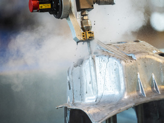
With jet diameters down to 150 µm, micro waterjet cutting developed by the Swiss company Waterjet is much more precise than the 800 µm technology commonly used in the industry. On the earlier F4 series machines, the working area was limited to 600 x 1,000 mm in order to be able to guarantee the specified accuracy. Advances in mechanical engineering now make it possible to cut sheets in the standard 2,000 x 1,000 mm format with the same precision using the new “M5”.
© Klaus Vollrat
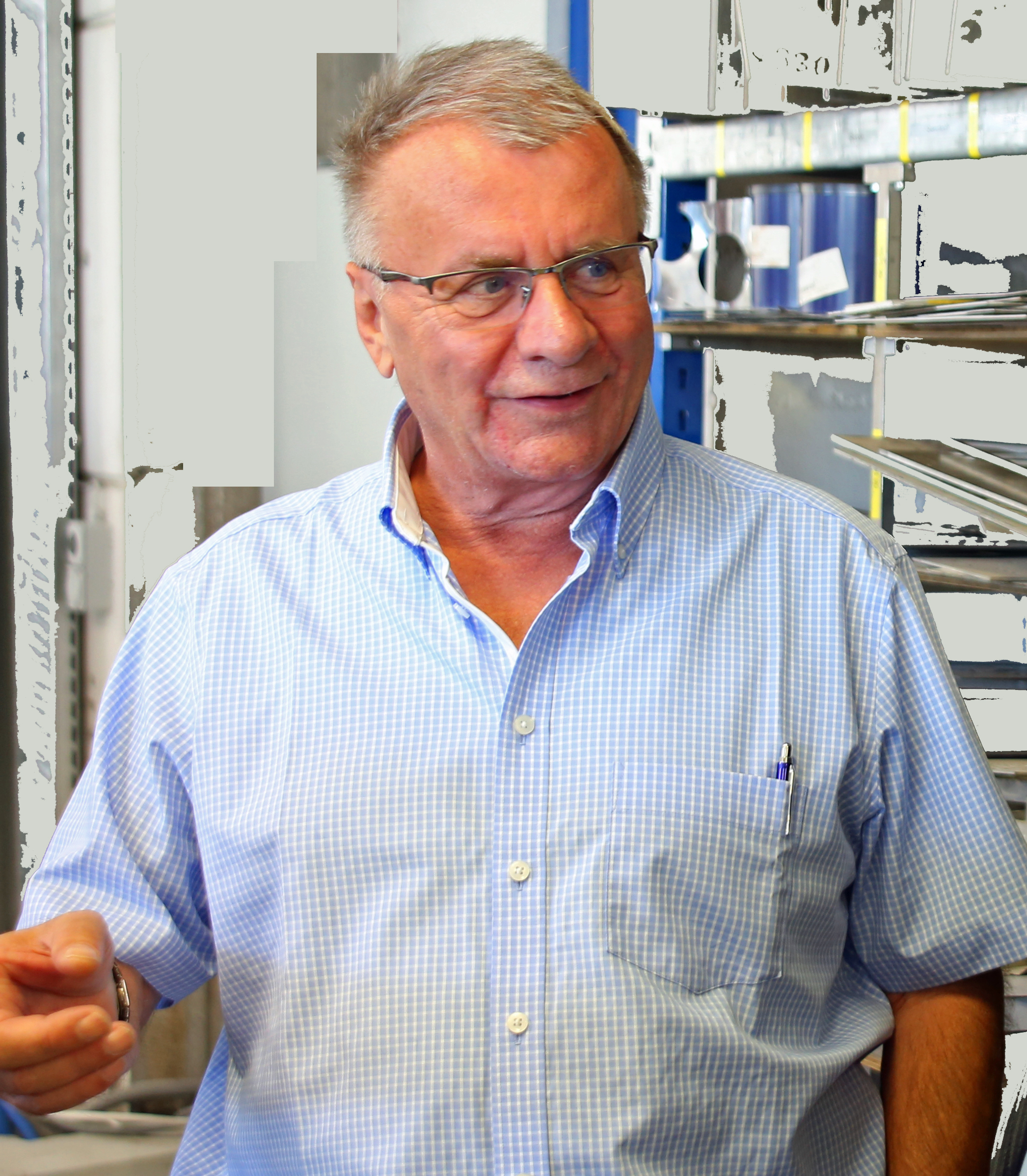
“The previous limitation of the working range of our F4 machines caused both technical and economic disadvantages,” explains Walter Maurer, founder and Chairman of the Board of Waterjet AG in Aarwangen (Switzerland). This already started with the time required for multiple cutting of the boards, which are commercially supplied in 2,000 x 1,000 mm format. In addition, a 200 mm wide residual strip remained afterwards, which often enough ended up in the scrap.
If parts with larger dimensions had to be produced despite the size limitations of the work area, a sheet with the corresponding oversize was clamped and offset by the required distance after an initial machining pass. However, reclamping inevitably results in misalignment and angular errors and corresponding quality losses on the workpiece.
Even more serious, however, is the loss of material due to the “edge effect” when nesting parts on the work surface. The material-saving arrangement of the parts on the sheet is more restricted the larger the parts are in relation to the dimensions of the work surface. In unfavorable cases, these grid losses can reach values of over 50 percent, which is well above the usual average of 30 percent. And last-not-least, depending on the job characteristics, a larger machine can run unmanned for much longer, even after the end of a shift or into the weekend.
Precision mechanical engineering for highest accuracy
“With the considerably larger dimensions of the new system, we had to come up with quite a few ideas to ensure at least the same accuracy values as the previous F4 version,” reveals W. Maurer. This already starts with the machine bed: This consists of a chromium steel construction, which was filled with eight tons of vibration-damping mineral concrete.
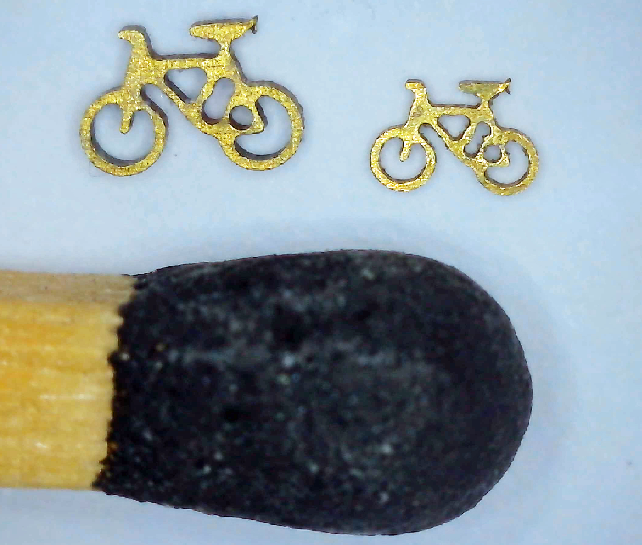
The three main axes have high-precision ball screws and position measurement is performed by temperature-insensitive glass measuring rods with a resolution of ten nanometers. The workpiece carrier is mechanically decoupled from the water basin and the vibrations occurring in it. The repeatability of the axes is 0.5 µm. The new nozzles with a cutting jet diameter of only 150 µm are also used on the line. This allows cutting gap widths of only 170 µm to be achieved with suitably thin material. Accuracies of up to 5 µm can be achieved on the workpiece.
For mechanical machining, the workhead can additionally be equipped with a high-frequency drilling spindle with its own Z-axis. This also allows starting holes to be drilled in laminated materials such as glass or carbon fiber composites. If one were to attempt to create such boreholes with the ultrahigh-pressure water jet instead, material damage due to delamination could occur.
© Kunz Precision
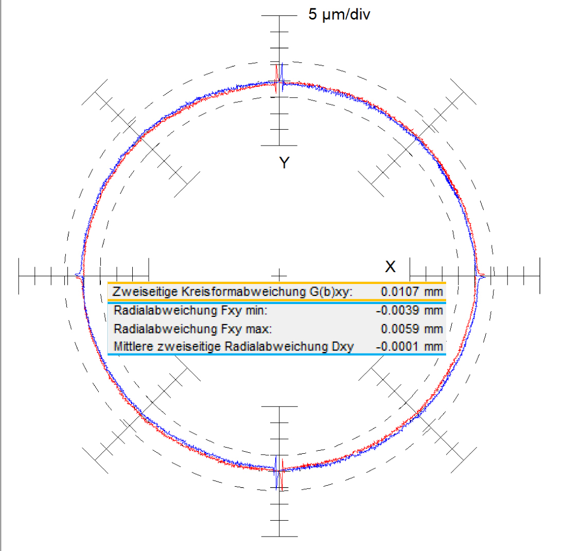
More accurate thanks to shape analysis of the water jet
“Based on precise investigations, we know that the waterjet is never exactly round. The roundness deviations are up to 3 µm,” explains Walter Maurer. To take this into account, the exact geometry of the water jet is determined using a patented process after a new nozzle has been installed. For this purpose, a hole with a diameter of 2 mm is created in a sheet, the geometry of which is precisely measured under a high-precision measuring microscope. The roundness deviations registered in the process are stored in the control as a function of the angle and compensated for during use. For this purpose, the actual contour of the waterjet is guided tangentially to the desired outer contour of the workpiece in each case. The prerequisite for this is that the CAM software can distinguish between the workpiece side and the rest grid side.
Contour-dependent adaptation of the working parameters
“With the CAM software, we can adapt the working parameters to specific requirements of certain areas of the part contour,” Walter Maurer further explains. An example is cutting sharp corners or narrow gaps, for which the cutting speed is reduced in order to follow the part contour really cleanly. However, this slowing down would result in an undesirable widening of the kerf if the working pressure of the waterjet remains constant. In such cases, the machine control system enables an additional “trick” by reducing the pressure of the cutting jet accordingly in this area. That is why the M5 includes a modern high-pressure pump with servo drive. This combination also makes it possible to temporarily lower the pressure during certain operations, such as piercing, to reduce adverse effects such as the undesirable upward splashing of abrasive-laden water.
Another special feature of the control is the option to create high-precision holes in two passes. In the first operation, most of the bore is cut free at maximum working speed so that only a small residual wall thickness remains. In a second pass, this is then machined out with the greatest possible precision at a lower speed, making maximum use of the possibilities for adjusting the shape of the beam. The procedure can be roughly compared to the roughing and finishing passes in milling. The advantage is a more vertical cut edge with a smoother surface.
A special feature of these strategies is the interaction of CAM software (Bysoft) and special MWJ tools in the Beckhoff controller of the M5. For this purpose, the programmer in the work preparation department marks the desired parts of the part contour with corresponding macros. These are then recognized by the controller and implemented accordingly by the MWJ tool.
© Klaus Vollrath
A maximum of process control
“Our customers include industries such as medical technology, which place the highest demands on their suppliers in terms of the reproducibility of the processes used,” knows W. Maurer. The M5 can also meet these requirements. For each machine, the machine and process capability is determined on the basis of test machining, for example on 2-mm chromium steel sheets, with Cpk values of 1.33 being targeted. In addition, concepts for optimizing cut edge quality are being worked on.
As a further measure, the plant control system offers the option of archiving all parameters of the process in the form of a PDF file so that they can still be assigned to the parts produced with them at a later date. As a further function, the archiving of these parameter sets in a so-called MEF file is possible. This file is also archived and, when called up, reproduces exactly all the machine settings selected at the time, so that the manufacturing process for repeat parts can be reproduced in every detail.
Web:
www.waterjet.ch